A fuel cell is an electrochemical device that directly converts the chemical energy of reactants (a fuel and an oxidant) into electricity. In this way, the intrinsic efficiency of such an electrochemical converter is not subject to the Carnot limitation and can be much higher than conventional thermal engines. The emission of air pollutants will be significantly minimised.
|
A schematic presentation of the principle is illustrated in Figure 1 for an acid electrolyte fuel cell. Hydrogen is catalytically oxidized at the anode to give protons and electrons. Since the electrolyte is a non-electronic conductor, the electrons flow away from the anode via the external circuit to the cathode. The protons pass through the electrolyte to the cathode, where the oxygen gas reacts with the incoming electrons and protons to produce water.The overall reaction of the fuel cell is the sum of the anode and cathode reactions, i.e. the combination of hydrogen and oxygen to produce water and energy:
|
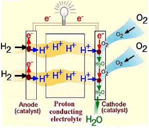
Figure 1. Principle of a fuel cell
|
| Anodic reaction: |
H2 → 2 H+ + 2e- |
E0anode = 0 |
| Cathodic reaction: |
½O2 + 2e- + 2H+ → H2O |
E0cathode = 1.229 V |
| Overall reaction: |
H2 + ½O2 → 2H2O |
E0cell = 1.229 V |
Fuel cells are generally classified according to the electrolyte and its ionic conductivity, which can be hydrogen ions or protons (H+) in Polymer Electrolyte Membrane Fuel Cells (PEMFC) and Phosphoric Acid Fuel Cells (PAFC), or hydroxyl ions (OH-) in Alkaline Fuel Cells (AFC), or carbonate ions (CO32-) in Molten Carbonate Fuel Cells (MCFC) or oxide (O2-) in Solid Oxide Fuel Cells (SOFC). The PEMFC is attractive for portable electronics and transportation applications, and is a major competitor for stationary power applications less than 100kW.
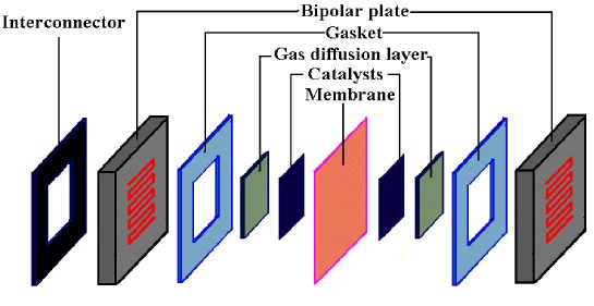
An exploded view of PEMFC components is shown in Figure 2 below. The components include:
- the ion exchange membrane;
- an electrically conductive porous backing layer;
- a catalyst layer (the electrodes) sandwiched between the backing layer and the membrane;
- gaskets for gas tight seal and electrical insulation;
- cell plate hardwares with gas channels on one side (end plates or plates for single cells) or on both sides (bipolar plates) that delivers the fuel and oxidant to the reactive sites;
- other materials for e.g. interconnecting, cooling, manifold and others.
In close collaboration with Danish and European R&D groups and industries, we are developing materials, components, stacks, and power systems through national and European projects.
 |
|
Figure 2. An exploded view of PEMFC components.
|
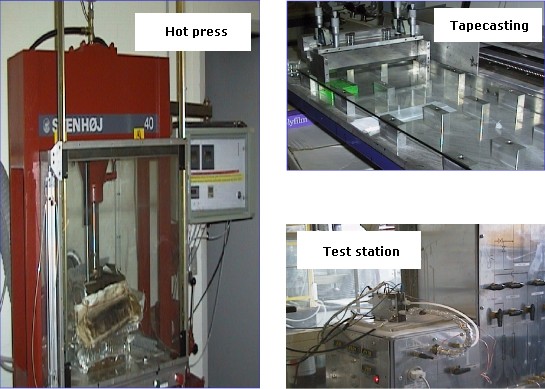
Some instruments for fabricating and testing the PEMFC components such as tape-casting machine, hot-press and test station are shown in Figure 4.
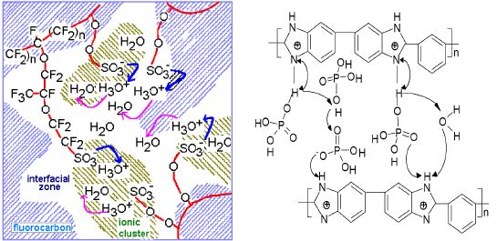
The key component in a PEM fuel cell is the proton exchange membrane. The most widely used is perfluorosulfonic acid (PFSA) membranes with perfluorinated backbones and sulfonic acid as the terminal group, as schematically shown in Fig. 3 (left). The membrane conductivity is dependent on a certain amount of absorbed water on the sulfonic sites. This strong dependence of conductivity on water content makes it necessary for the PEMFC system to carefully manage the water balance through evaporation and condensation of water at a temperature close to its boiling point. This links up the air humidity, airflow rate, system pressure and stack temperature during the PEMFC construction and operation. The presence of water in the system also limits the operational temperature, typically set at 80°C. At this temperature, the PEMFC has poor tolerance to fuel impurities (e.g. CO), which results in bulky and complex fuel processing units for CO cleanup when hydrocarbons or alcohols are used as fuel via reforming.
Here at DTU we are working with a new type of membranes based on phosphoric acid doped polybenzimidazoles (PBI), see Fig 3 (right). This membrane involves a different mechanism of proton conduction and possesses high proton conductivity even with very low water content. As a result, PEMFC based on this type of membranes can operate at temperatures up to 200°C without any gas humidification. The high operating temperature allows for a CO tolerance of up to several percent. A lifetime of continuous operation for over 5000 hours at 150°C and shutdown-restart thermal cycling test for more than 200 cycles has been achieved.
 |
|
Figure 3. Schematic presentation of proton conduction in perfluorosulfonic acid (left) and acid-doped polybenzimidazole (right) membranes.
|
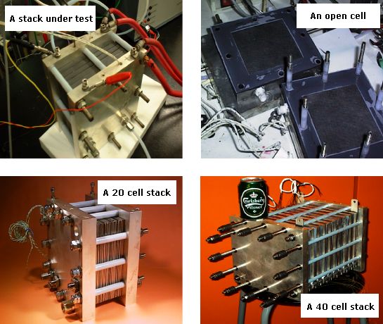
Some facilities of the group for PEMFC fabrication and tests are shown in Fig. 4 Examples of single cells and stacks developed in the group are shown in Figure 5.
 |
|
Figure 4. Instruments for fabricating and testing the PEMFC components.
|
 |
|
Figure 5. Examples of single cell and stack developed by the group.
|
Through years the group has been involved in many national and international research projects. Numerous publications in the field of fuel cells are available by the group. The current research activities of the group cover the following materials and technological aspects
- Polymer synthesis
- Functionalization of polymers
- Membrane development
- Physiochemical characterization of membrane (conductivity, mechanical strength, gas permeability, etc.)
- Electrocatalyst fabrication and charaterizations
- Gas diffusion electrodes
- Membrane-electrode assemblies (MEAs)
- Single fuel cell tests (hydrogen fuel cells and direct methanol fuel cells)
- Stack design and construction
- Natural gas reforming
- Methanol reforming
For further information contact: Qingfeng Li, Niels J. Bjerrum, or Jens Oluf Jensen